
Stainless Steel Welding Process Selection: TIG vs MIG vs SAW vs Laser — Technical Parameters & Comparison Guide
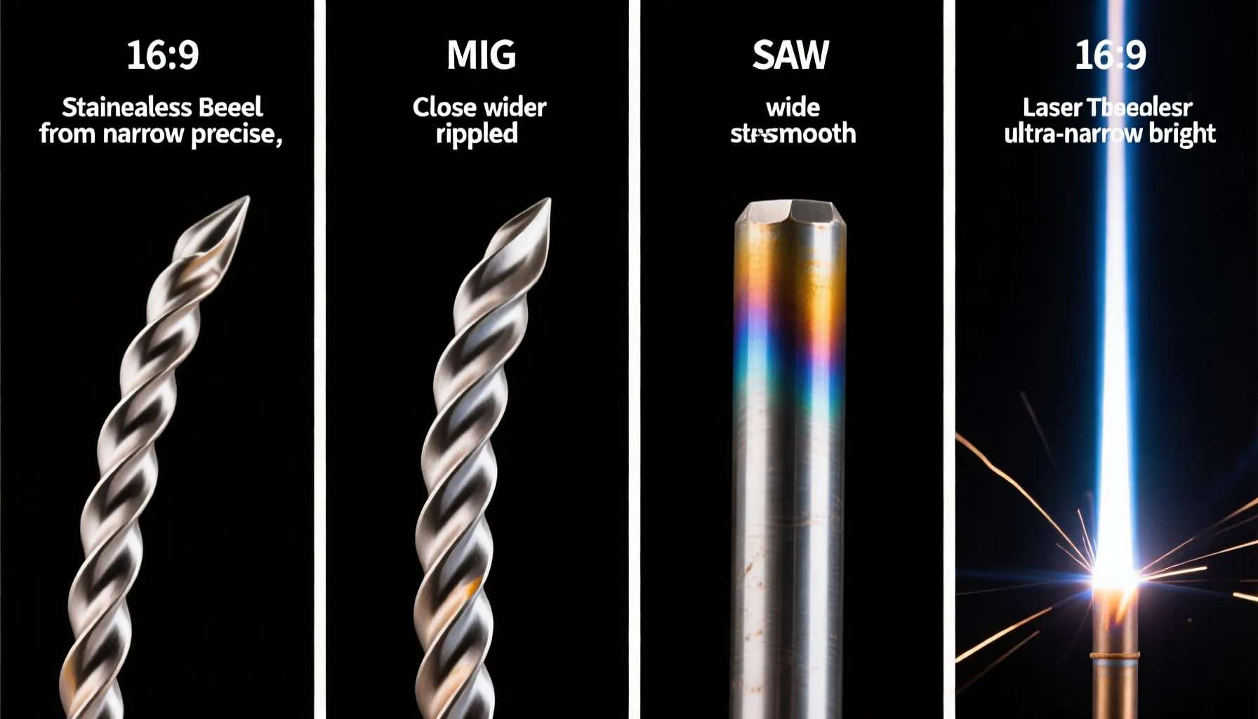
Stainless steel welding process selection is one of the most consequential decisions a fabrication engineer makes — it directly determines weld quality, production throughput, post-weld rework costs, and long-term corrosion performance. At Zeming Steel, our factory floor runs four welding processes daily across 300-series, duplex, and super-austenitic grades: TIG (GTAW) for root passes and thin-gauge precision work, MIG (GMAW) for structural and production welding, SAW for heavy-wall vessels and long seams, and laser welding for high-speed automated thin-sheet production. Each process occupies a distinct window of thickness, speed, cost, and quality. Choosing the wrong one means rework, sensitization, or field failure.
This guide builds on our comprehensive welding process selection pillar resource and distills the key decision data: technical parameters for each process (amperage ranges, shielding gas flow rates, travel speeds), a side-by-side comparison matrix, filler metal and shielding gas selector tables, critical process controls (back purge, interpass temperature, heat input limits), and a practical defect-prevention reference you can use on the shop floor today.
Whether you are specifying a weld procedure for an ASME Section IX-qualified pressure vessel or optimizing a production line for stainless steel tanks, this guide provides the engineering data to make the right call.
TIG Welding (GTAW) — Precision for Stainless Steel Pipe and Thin Sheet
How It Works
Gas Tungsten Arc Welding (GTAW/TIG) uses a non-consumable tungsten electrode to generate an arc under inert gas shielding — typically pure argon or an argon-helium blend. Filler metal is hand-fed separately, giving the welder independent control over heat input and deposition rate. This separation is what makes TIG the highest-quality stainless steel welding process: the weld pool is always visible, the arc is stable down to single-digit amperage, and there is zero spatter.
Best Applications
- Pipe root passes: TIG is the industry standard for open-root butt welds on stainless steel pipe (SCH 10 through SCH 160). The precise puddle control guarantees full penetration with a smooth, sugaring-free internal bead when backed by an argon purge.
- Thin sheet (0.5–3.0 mm): No other arc process can match TIG at low amperages for 304 and 316L sheet metal. With inverter machines capable of 5 A starts, burn-through risk is near zero in skilled hands.
- Sanitary tubing and food-grade welds: The absence of spatter and flux residue makes TIG the only acceptable process for dairy, pharmaceutical, and semiconductor gas lines where internal surface finish is critical.
- Duplex and super-austenitic alloys: TIG provides the controlled heat input (typically 0.5–1.5 kJ/mm for duplex) required to preserve the austenite-ferrite phase balance.
Technical Parameters for 304/316L
| Parameter | Thin Sheet (0.5–1.5 mm) | Medium Plate (1.5–4.0 mm) | Heavy Plate / Pipe Root (4.0–10.0 mm) |
|---|---|---|---|
| Current (DCEN) | 5–50 A | 50–150 A | 100–250 A |
| Electrode (EWTh-2 / EWCe-2) | 1.0–1.6 mm | 1.6–2.4 mm | 2.4–3.2 mm |
| Shielding Gas Flow | 6–10 L/min (Ar) | 8–14 L/min (Ar / Ar+He) | 10–18 L/min (Ar+He) |
| Back Purge Flow | 3–5 L/min (Ar) | 5–8 L/min (Ar) | 8–12 L/min (Ar) |
| Travel Speed | 50–150 mm/min | 80–200 mm/min | 60–150 mm/min |
| Heat Input Target | 0.3–0.8 kJ/mm | 0.5–1.2 kJ/mm | 0.8–1.8 kJ/mm |
Pros and Cons
| Pros | Cons |
|---|---|
| Highest weld quality — radiographic-grade soundness | Slowest deposition rate (0.2–1.5 kg/hr) |
| Zero spatter, minimal post-weld cleaning | High operator skill required (months to certify) |
| Independent control of heat and filler — ideal for dissimilar alloys | Not economical for plate >10 mm except for root passes |
| Works in all positions (1G through 6G) | Sensitive to wind/drafts — shielding gas disruption causes porosity |
| No flux = no slag entrapment risk | Lower productivity vs. MIG or SAW for production welding |
MIG Welding (GMAW) — Production Speed for Structural Stainless Steel
How It Works
Gas Metal Arc Welding (GMAW/MIG) feeds a continuously-spooled wire electrode through a contact tip into the weld pool, with shielding gas delivered concentrically through the nozzle. The wire serves as both electrode and filler metal, making the process semi-automatic. For stainless steel, MIG typically runs in spray-transfer or pulsed-spray mode — short-circuit transfer is limited to thin sheet and positional work where lower heat input is needed.
Best Applications
- Structural stainless steel fabrication: Beams, columns, frames, and platforms in 304/316L — MIG provides the deposition rate (3–8 kg/hr) to make these jobs profitable while maintaining structural code compliance per AWS D1.6/D1.6M.
- Thick plate production welding: For plate from 3 mm to 25 mm, pulsed MIG delivers a favorable balance of deposition rate, penetration, and heat input control.
- Pressure vessel shell courses: Where TIG root + MIG fill/cap is the standard combination for stainless steel boiler and stainless steel tank longitudinal and circumferential seams.
- High-volume repetitive weldments: Robotic or mechanized MIG cells can sustain 80–100% arc-on time.
Technical Parameters for 304/316L
| Parameter | Short-Circuit (0.8–3.0 mm) | Spray Transfer (3.0–12.0 mm) | Pulsed Spray (1.5–25.0 mm) |
|---|---|---|---|
| Wire Diameter | 0.8–1.0 mm | 1.0–1.6 mm | 1.0–1.2 mm |
| Current (DCEP) | 50–180 A | 180–350 A | 40–280 A (avg.) |
| Voltage | 14–22 V | 25–35 V | 18–30 V |
| Shielding Gas | Ar + 2% CO₂ / Ar + 2% O₂ | Ar + 2% O₂ / Ar + He + CO₂ tri-mix | Ar + 2% CO₂ / Ar + 2% O₂ |
| Gas Flow | 12–18 L/min | 15–22 L/min | 14–20 L/min |
| Wire Feed Speed | 2–8 m/min | 6–16 m/min | 3–12 m/min |
| Deposition Rate | 1–3 kg/hr | 4–8 kg/hr | 2–7 kg/hr |
Pros and Cons
| Pros | Cons |
|---|---|
| High deposition rate — 3–8× faster than TIG | Spatter generation (reduced but not eliminated with pulsed MIG) |
| Lower operator skill floor vs. TIG | Active gas component (CO₂/O₂) can cause slight weld oxidation |
| Semi-automatic = consistent bead profile | Not ideal for root passes without backing — risk of lack of fusion |
| Wide thickness range with mode switching | Higher heat input (0.8–2.5 kJ/mm) — caution on duplex/super-austenitic grades |
| Well-suited for robotic automation | Limited out-of-position capability in spray transfer (1G/1F primarily) |
Submerged Arc Welding (SAW) — Heavy-Wall Stainless Steel Vessels and Long Seams
How It Works
Submerged Arc Welding (SAW) feeds a continuous solid or metal-cored wire beneath a blanket of granular flux. The arc is fully submerged — there is no visible arc light, no spatter, and no fume generation at the operator position. The flux serves triple duty: it shields the molten metal from atmosphere, it deoxidizes and refines the weld pool, and it can alloy the deposit (e.g., chromium compensation for dilution). SAW operates exclusively in the flat (1G) and horizontal (2F) positions, and its extremely high deposition rate — 8 to 25 kg/hr with a single wire and up to 40 kg/hr with tandem-wire setups — makes it unmatched for heavy-section stainless steel fabrication.
Best Applications
- Pressure vessels and storage tanks: SAW is the standard process for welding shell courses on large-diameter stainless steel tanks, where longitudinal and circumferential seams run 5 to 20 meters in a single setup.
- Thick plate (15–80+ mm): SAW achieves full penetration on heavy plate in fewer passes than any alternative arc process, with deep penetration (up to 20 mm in a single pass with single wire).
- Cladding and overlay: SAW strip cladding (60–120 mm wide strip electrodes) is used to apply stainless steel corrosion-resistant overlays on carbon steel substrates — common in chemical pressure vessels.
- Long, straight seams: Any application where a part can be positioned flat for the duration of the weld — boiler shells, wind tower sections, ship panels, bridge girders.
Technical Parameters for 304/316L
| Parameter | Single Wire (6–20 mm plate) | Tandem Wire (20–50 mm plate) |
|---|---|---|
| Current (DCEP / AC) | 400–1,200 A | Lead: 800–1,200 A DC / Trail: 600–900 A AC |
| Voltage | 28–38 V | 28–40 V (lead), 30–42 V (trail) |
| Wire Diameter | 2.4–4.0 mm | 3.2–4.0 mm (both wires) |
| Travel Speed | 300–800 mm/min | 400–1,200 mm/min |
| Deposition Rate | 8–18 kg/hr | 15–40 kg/hr |
| Flux Type | Neutral / neutral-basic (CaF₂-Al₂O₃) | Neutral-basic (low Si pickup preferred) |
| Heat Input | 1.5–3.5 kJ/mm | 2.0–4.5 kJ/mm |
Pros and Cons
| Pros | Cons |
|---|---|
| Highest deposition rate of all arc processes (8–40 kg/hr) | Restricted to flat (1G) and horizontal (2F) positions |
| Deep penetration — reduces total pass count on thick plate | Flux handling, storage, and recycling required (moisture control critical) |
| Zero visible arc, no spatter, low fume at operator station | High heat input — risk of grain growth and sensitization on unstabilized grades |
| Excellent slag detachment with properly formulated fluxes | Joint access limited — parts must be positionable |
| Ideal for long uninterrupted seams | Slag inclusion risk if inter-pass cleaning is skipped |
Laser Welding — High-Speed Precision for Automated Stainless Steel Production
How It Works
Laser beam welding (LBW) focuses a high-power-density laser beam — typically a fiber laser (1,070 nm) or disk laser — onto the workpiece through optics or a galvo scanner. The concentrated energy (10⁴–10⁶ W/mm²) creates a deep, narrow keyhole, producing a weld with an exceptionally high depth-to-width ratio. For stainless steel, laser welding can be performed autogenously (no filler) on tight-fit-up joints or with cold/hot wire feed for gap bridging. Modern multi-kilowatt fiber lasers (6–20 kW) can weld stainless steel at travel speeds of 3–12 m/min — an order of magnitude faster than TIG.
Best Applications
- Automated thin-sheet production: For 0.3–3.0 mm stainless steel sheet (304, 316L, 430), laser welding achieves full penetration at 4–8 m/min with near-zero distortion — ideal for appliance panels, architectural cladding, and automotive exhaust components.
- Precision components: Medical devices, sensor housings, battery enclosures, and bellows where the heat-affected zone (HAZ) must be measured in tenths of a millimeter.
- Tube and profile welding: Laser-welded stainless steel tube mills produce continuous tube at 10–30 m/min with a weld bead that requires minimal scarfing.
- Dissimilar-material joints: Laser’s precisely positioned energy enables controlled dilution when welding stainless steel to nickel alloys or titanium.
Technical Parameters for 304/316L
| Parameter | Thin Sheet (0.3–1.5 mm) | Medium Sheet (1.5–4.0 mm) | Thick Plate (4.0–12.0 mm) |
|---|---|---|---|
| Laser Power | 0.5–2 kW | 2–6 kW | 6–20 kW |
| Travel Speed | 3–8 m/min | 1.5–5 m/min | 0.5–3 m/min |
| Shielding Gas | Argon (root + top), N₂ (austenitic grades), or He (high-speed) | ||
| Gas Flow (coaxial) | 10–20 L/min | 15–30 L/min | 20–40 L/min |
| Focal Position | 0 to −1 mm (at/just below surface) | −1 to −3 mm (below surface) | −2 to −5 mm (below surface) |
| Spot Size | 0.1–0.3 mm | 0.3–0.6 mm | 0.4–0.8 mm |
| Heat Input | 0.015–0.08 kJ/mm | 0.04–0.20 kJ/mm | 0.10–0.50 kJ/mm |
Pros and Cons
| Pros | Cons |
|---|---|
| Fastest travel speed — 3–12 m/min (10–50× TIG) | Very high capital cost ($200K–$1M+ for industrial system) |
| Minimal HAZ and distortion — <0.5 mm HAZ typical | Tight fit-up required (gap <0.1 mm or 10% of thickness for autogenous) |
| Deep, narrow welds — aspect ratio up to 10:1 | Sensitive to reflectivity — aluminum and copper are challenging |
| Excellent repeatability — CNC-controlled galvo or gantry | High solidification rate can cause centerline cracking in fully austenitic grades |
| Autogenous welding possible on tight-fit-up joints | Laser safety enclosure required (Class 1 or Class 4 controlled area) |
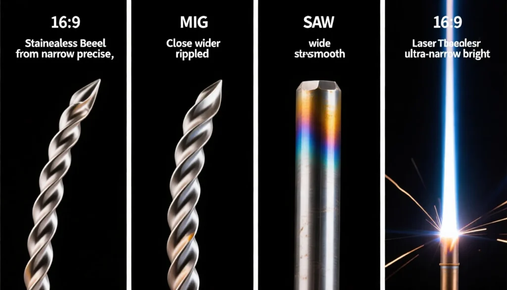
TIG vs MIG vs SAW vs Laser — Complete Comparison Matrix (8 Rows × 4 Columns)
The table below provides a quantitative side-by-side comparison of the four major stainless steel welding processes across eight critical engineering dimensions. Use this matrix as the primary reference when performing stainless steel welding process selection for a specific application.
| Parameter | TIG (GTAW) | MIG (GMAW) | SAW | Laser (LBW) |
|---|---|---|---|---|
| 1. Welding Speed | 50–200 mm/min | 200–800 mm/min | 300–1,200 mm/min | 500–12,000 mm/min |
| 2. Cost per Meter (relative, incl. labor) | $$$$ (highest — slow + skilled labor) | $$ (moderate — fast, semi-automatic) | $ (lowest — high deposition, low labor) | $$$ (moderate-high — equipment amortization) |
| 3. Weld Quality (radiographic) | Excellent — RT-grade with certified operator | Good to Very Good — porosity risk without proper gas coverage | Very Good — consistent, deep penetration, low defect rate | Excellent — near-perfect profile, minimal defects with proper fit-up |
| 4. Thickness Range | 0.5–6 mm (single pass) Root pass: any thickness |
0.8–25 mm (mode-dependent) |
6–80+ mm (multi-pass) |
0.3–12 mm (single pass, conduction or keyhole) |
| 5. Heat Input (kJ/mm) | 0.3–1.8 | 0.5–2.5 | 1.2–4.5 | 0.015–0.50 |
| 6. Distortion Risk | Moderate (slow travel = heat buildup) | Moderate-High (depending on mode) | High (large HAZ, requires straightening) | Very Low (minimal total heat input) |
| 7. Operator Skill Required | Very High (months to certify 6G pipe) | Low-Moderate (weeks to basic proficiency) | Low-Moderate (setup-critical, forgiving in operation) | Low (operator loads part, presses cycle) |
| 8. Typical Applications | Pipe root passes, sanitary tube, thin sheet, aerospace, nuclear | Structural frames, vessel shells (fill/cap), general fabrication | Pressure vessel seams, tank courses, beam splicing, cladding | Appliance panels, medical devices, tube mills, EV battery enclosures |
Critical Welding Parameters for Stainless Steel — Process Controls That Determine Weld Integrity
Beyond selecting the right process, several cross-cutting parameters govern whether a stainless steel weld will meet its design life in corrosive service. These controls apply regardless of the welding method chosen, and they are mandatory for code-compliant fabrication under ASME Section IX and AWS D1.6/D1.6M.
Back Purge Requirements
Definition — Back Purge: The practice of flooding the root side (inside) of a pipe, tube, or single-sided butt joint with an inert gas — typically argon — to displace atmospheric oxygen and prevent chromium oxide formation (sugaring) on the root bead. Without back purge, the weld root oxidizes instantly at temperature, losing corrosion resistance and creating a brittle, porous surface that can initiate crevice corrosion in service.
| Parameter | Recommendation |
|---|---|
| Purge Gas | Argon (99.99%+), Ar + 5–10% H₂ (for 300-series only — improves wetting, reduces oxide) |
| Flow Rate | 5–12 L/min (adjust for pipe/tube internal volume — target 6–10 volume changes before welding) |
| Residual O₂ Target | <0.05% (500 ppm); <0.01% (100 ppm) for hygienic/semiconductor service |
| Purge Duration | Pre-purge: 3–5× internal volume displacement. Post-purge: maintain until root temperature <250 °C |
| Verification | Oxygen analyzer with probe at weld zone exit point — do not rely on purge time alone |
Interpass Temperature Control
Definition — Interpass Temperature: The temperature of the weld zone immediately before depositing the next pass in a multi-pass weld. For austenitic stainless steels (304/316L), the interpass temperature must be kept at or below 150 °C (300 °F). For duplex stainless steels (2205, 2507), the limit is tighter: 100–150 °C maximum, with a minimum interpass of approximately 20 °C to avoid excessive ferrite. Exceeding these limits prolongs time in the sensitization temperature range (450–850 °C), where chromium carbides precipitate at grain boundaries, depleting the adjacent matrix of chromium and destroying intergranular corrosion resistance — a phenomenon known as sensitization.
Heat Input Control
Definition — Heat Input (kJ/mm): The electrical energy delivered to the weld per unit length, calculated as:
Heat Input (kJ/mm) = (Voltage × Amperage × 60) / (Travel Speed × 1,000)
For austenitic stainless steels, target heat input below 1.5 kJ/mm to minimize grain growth in the HAZ and keep interpass temperature manageable. For duplex grades, the window is narrower: 0.5–1.5 kJ/mm is typically specified to maintain the target 40–60% ferrite content. Excessively low heat input (below 0.3 kJ/mm) can cause excessively high cooling rates in duplex, leading to excessive ferrite and reduced toughness.
Filler Metal Selection Table
Matching the filler metal to the base alloy is critical — a mismatch can produce a weld with inferior corrosion resistance or mechanical properties. The table below covers the most common stainless steel grades processed at our facility through our stainless steel processing operations.
| Base Metal (Grade) | Filler Metal (AWS A5.9) | Filler Metal (EN ISO 14343) | Key Notes |
|---|---|---|---|
| 304 / 304L | ER308L | G 19 9 L | Standard austenitic filler. Low carbon (≤0.03%) prevents intergranular carbide precipitation. |
| 316 / 316L | ER316L | G 19 12 3 L | 2–3% Mo for pitting resistance in chloride environments. Low carbon variant mandatory for service >350 °C. |
| 304H / 316H | ER308H / ER316H | G 19 9 H / G 19 12 3 H | High carbon (0.04–0.08%) for creep strength in elevated-temperature service. |
| 309 / 309S | ER309L | G 23 12 L | Higher Cr+Ni for welding 304 to carbon steel (dissimilar joints) — compensates for dilution. |
| 310 / 310S | ER310 | G 25 20 | Full-austenitic deposit — 25% Cr / 20% Ni for high-temperature oxidation resistance up to 1,100 °C. |
| 321 | ER347 (preferred) or ER321 | G 19 9 Nb | Niobium-stabilized — ER347 provides better hot-cracking resistance than ER321 in restrained joints. |
| 347 | ER347 | G 19 9 Nb | Nb-stabilized to prevent sensitization at 450–850 °C service. |
| 2205 (Duplex) | ER2209 | G 22 9 3 N L | Over-alloyed in Ni (~8.5%) vs. base metal (~5.5%) to ensure austenite-ferrite balance in the as-welded deposit. |
| 2507 (Super Duplex) | ER2594 | G 25 9 4 N L | Higher Cr+Mo+Ni+Ni for matching pitting resistance equivalent number (PREN >40) in the weld. |
| 904L | ER385 | G 20 25 5 Cu L | High Ni + Cu + Mo for sulfuric acid service. |
Shielding Gas Selection Guide
Shielding gas choice impacts arc stability, bead profile, spatter levels, and — critically for stainless steel — the final weld surface oxidation and corrosion resistance. The table below summarizes recommended shielding gas mixtures for each welding process.
| Process | Recommended Gas(es) | Typical Flow Rate | Notes |
|---|---|---|---|
| TIG (GTAW) | 100% Ar (standard) Ar + 2–5% H₂ (austenitic only) Ar + 25–75% He (thick section / high-speed) |
6–18 L/min | H₂ improves wetting and travel speed but causes hydrogen embrittlement in ferritic/martensitic grades. He blend increases heat input for thick sections. |
| MIG (GMAW) | Ar + 2% CO₂ (general) Ar + 1–2% O₂ (spray transfer) Ar + He + CO₂ tri-mix (heavy section, pulsed) |
12–22 L/min | Keep CO₂ ≤2% to minimize carbon pickup. O₂ at 1–2% stabilizes the arc and improves wetting without excessive surface oxidation. |
| SAW | Flux only (no external gas) Flux type: neutral or neutral-basic |
N/A (flux blanket) | Flux formulation controls weld metal chemistry. For 304/316L, specify Cr-compensating fluxes. Store and re-dry flux per manufacturer (typically 250–350 °C for 2 hr). |
| Laser (LBW) | Argon (top + root shielding) N₂ (austenitic — enhances surface hardness) Helium (high-speed — suppresses plasma plume) |
10–40 L/min | Argon is the default. N₂ can dissolve into austenitic grades and slightly increase surface hardness. He is preferred at >5 m/min to suppress plasma above the keyhole. |
Post-Weld Treatment
Definition — Sensitization (Weld Decay): The precipitation of chromium-rich M₂₃C₆ carbides at austenite grain boundaries when stainless steel is held in the critical temperature range of 450–850 °C. This depletes the adjacent grain-boundary region of chromium (below the ~12% threshold required for passivity), making it susceptible to intergranular corrosion.
For welded stainless steel, post-weld treatment options include:
- Pickling and passivation: Chemical removal of the heat tint and chromium-depleted layer using nitric-hydrofluoric acid (pickling paste/gel), followed by nitric acid passivation to restore the passive chromium oxide film. This is mandatory for any stainless steel weld exposed to corrosive service.
- Solution annealing: For components that have been heavily sensitized (e.g., multi-pass SAW on thick 304), heating to 1,040–1,150 °C followed by rapid water quenching re-dissolves chromium carbides and restores full corrosion resistance. Only practical on components that can be furnace-treated.
- Mechanical cleaning: Stainless steel wire brushing (dedicated, uncontaminated brushes — never use a carbon steel brush), grinding, or glass-bead blasting to remove surface oxides. Must be followed by passivation.
6 Common Stainless Steel Welding Defects and Prevention
Regardless of which welding process you select through your stainless steel welding process selection, certain defects are inherent risks when working with austenitic and duplex grades. The table below identifies the six most common defect types, their root causes, and effective shop-floor countermeasures.
| # | Defect | Appearance | Root Causes | Prevention Measures |
|---|---|---|---|---|
| 1 | Lack of Fusion (LOF) | Incomplete bonding between weld metal and base metal or between passes — appears as a dark line on radiograph | Low amperage, excessive travel speed, incorrect electrode angle, oxide layer on joint faces, insufficient joint penetration preparation | Increase current by 10–20 A; reduce travel speed; ensure bevel angle ≥30° per side on butt joints; clean joint faces with acetone + stainless wire brush within 2 hr of welding |
| 2 | Porosity | Spherical gas voids (single or clustered) visible on radiograph or surface after light grinding | Inadequate shielding gas coverage (draft, low flow), moisture on filler wire or flux, hydrocarbon contamination on base metal, excessive stick-out in MIG | Use gas lens in TIG torch; verify gas flow with a flowmeter at the nozzle, not the regulator; maintain MIG stick-out at 10–15 mm; bake SAW flux at 300 °C × 2 hr; clean joint within 50 mm of weld zone with acetone |
| 3 | Sugaring (Root Oxidation) | Black, crystalline, granular oxide on the weld root — rough to touch, highly susceptible to corrosion | Insufficient or absent back purge; purge gas interrupted before root cooled below ~250 °C; excessive root gap allowing air ingress; oxygen contamination in purge gas line | Back purge with argon at 5–12 L/min; verify residual O₂ <0.05% with an oxygen analyzer at the exit point; maintain post-weld purge flow for 30–60 sec after arc extinguishes; use purge dams/diffusers for pipe welding |
| 4 | Hot Cracking (Solidification Cracking) | Centerline cracks in the weld bead (visible or subsurface) — common in fully austenitic welds with high restraint | Weld metal composition with ferrite number (FN) <3; high sulfur, phosphorus, or boron content; high restraint/high cooling rate; concave bead profile concentrating stress | Select filler metal with target FN 4–10 (e.g., ER308L over ER308); minimize sulfur and phosphorus in base and filler metal; maintain slightly convex bead profile; sequence welding to minimize restraint; preheat to 50–100 °C on thick sections to reduce cooling rate |
| 5 | Distortion | Angular, longitudinal, or buckling distortion — component will not meet dimensional tolerance after welding | Excessive heat input for joint configuration; unbalanced welding sequence; insufficient tack welding; thin material with wide HAZ; unrestrained joint design | Use lowest heat input process that meets penetration requirements (laser < TIG < MIG < SAW); apply balanced/double-sided welding sequence; increase tack weld frequency (every 50–100 mm); use strongbacks and jigs; pre-set parts to counter predicted distortion direction |
| 6 | Sensitization (Weld Decay) | No visible surface indication — manifests as intergranular corrosion in service, typically in HAZ 2–5 mm from fusion line | Prolonged time in 450–850 °C range during multi-pass welding; high carbon content (>0.03% in base metal); high heat input process on unstabilized grades (304, 316); inadequate interpass cooling | Specify “L” grade (304L, 316L) with carbon ≤0.03%; use stabilized grades (321, 347) for service at 450–850 °C; enforce interpass temperature ≤150 °C with temp sticks/thermocouple; minimize heat input to <1.5 kJ/mm on unstabilized grades; solution anneal at 1,040–1,150 °C if sensitization has occurred |
Frequently Asked Questions About Stainless Steel Welding Process Selection
Which welding process is best for thin stainless steel sheet?
TIG welding (GTAW) is the best choice for thin stainless steel sheet — typically 0.5 mm to 3 mm. Its precise heat control, low amperage capability (as low as 5 A with inverter machines), and excellent puddle visibility allow welders to avoid burn-through. Laser welding is an increasingly popular alternative for automated thin-sheet production where high travel speeds (2–6 m/min) and minimal distortion are critical.
What shielding gas should I use for stainless steel MIG welding?
For stainless steel MIG welding (GMAW), use Ar + 2% CO₂ or Ar + 2% O₂. The small oxidizing addition stabilizes the arc and improves wetting without causing excessive oxidation. Pure argon is not recommended for MIG because it produces an unstable arc and poor bead profile. For heavy-section spray transfer, a tri-mix of Ar + He + CO₂ (e.g., 65% Ar / 26.5% He / 8% CO₂ + 0.5% O₂) offers deeper penetration and faster travel speeds.
How do I prevent sugaring on stainless steel pipe welds?
Sugaring (severe oxidation on the weld root) is prevented by back purging — flooding the inside of the pipe or tube with an inert gas (typically argon) to displace oxygen. Maintain a back-purge flow rate of 5–10 L/min and continue purging until the root pass cools below approximately 250 °C. Verify purge effectiveness with an oxygen analyzer; residual O₂ should be below 0.05% (500 ppm) before striking an arc.
What is the maximum thickness SAW can weld in a single pass?
Submerged arc welding (SAW) can weld up to approximately 20 mm in a single pass with a single wire, and up to 40 mm with tandem-wire or multi-wire configurations. For stainless steel vessels and tanks at Zeming, we typically run SAW on plate thicknesses from 6 mm to 80 mm, using multiple passes with controlled interpass temperature (max 150 °C for austenitic grades) to preserve corrosion resistance.
Make the Right Stainless Steel Welding Process Selection for Your Next Project
Effective stainless steel welding process selection is not about finding the single “best” process — it is about matching the process to the specific requirements of thickness, joint configuration, production volume, corrosion service conditions, and available skilled labor. TIG delivers unmatched quality for root passes and thin-gauge work. MIG provides the production throughput that makes medium-to-heavy fabrication commercially viable. SAW remains the workhorse for thick-plate vessels and long seams where deposition rate drives project economics. Laser welding, while capital-intensive, offers transformative speed and precision for thin-sheet automated production.
At Zeming Steel, our welding engineering team qualifies procedures to ASME Section IX across all four processes, supported by in-house NDE (RT, UT, PT, PMI) and a metallurgical lab for ferrite measurement, corrosion testing, and macro/micro examination. Whether you need a single prototype weldment or 200 stainless steel tanks with SAW-welded shell courses, our factory has the process capability and engineering support to deliver code-compliant results on schedule.
Contact our engineering team at [email protected] or visit our processing capabilities page to discuss your welding requirements. Include your material grade, thickness range, joint configuration, and production volume for a technical recommendation and quotation within 24 hours.