
Ordering stainless steel gutters starts with a complete section drawing and a description of where the gutters will be used. Compare quotations on the same basis: grade, finished dimensions, fold details, weld requirements, inspection and the protected packing envelope.
This purchasing guide covers the decisions to settle before placing an order, including an assumed 1500 mm sheet-width example. It is not a drainage, support or structural design, and the example dimensions are not production instructions.
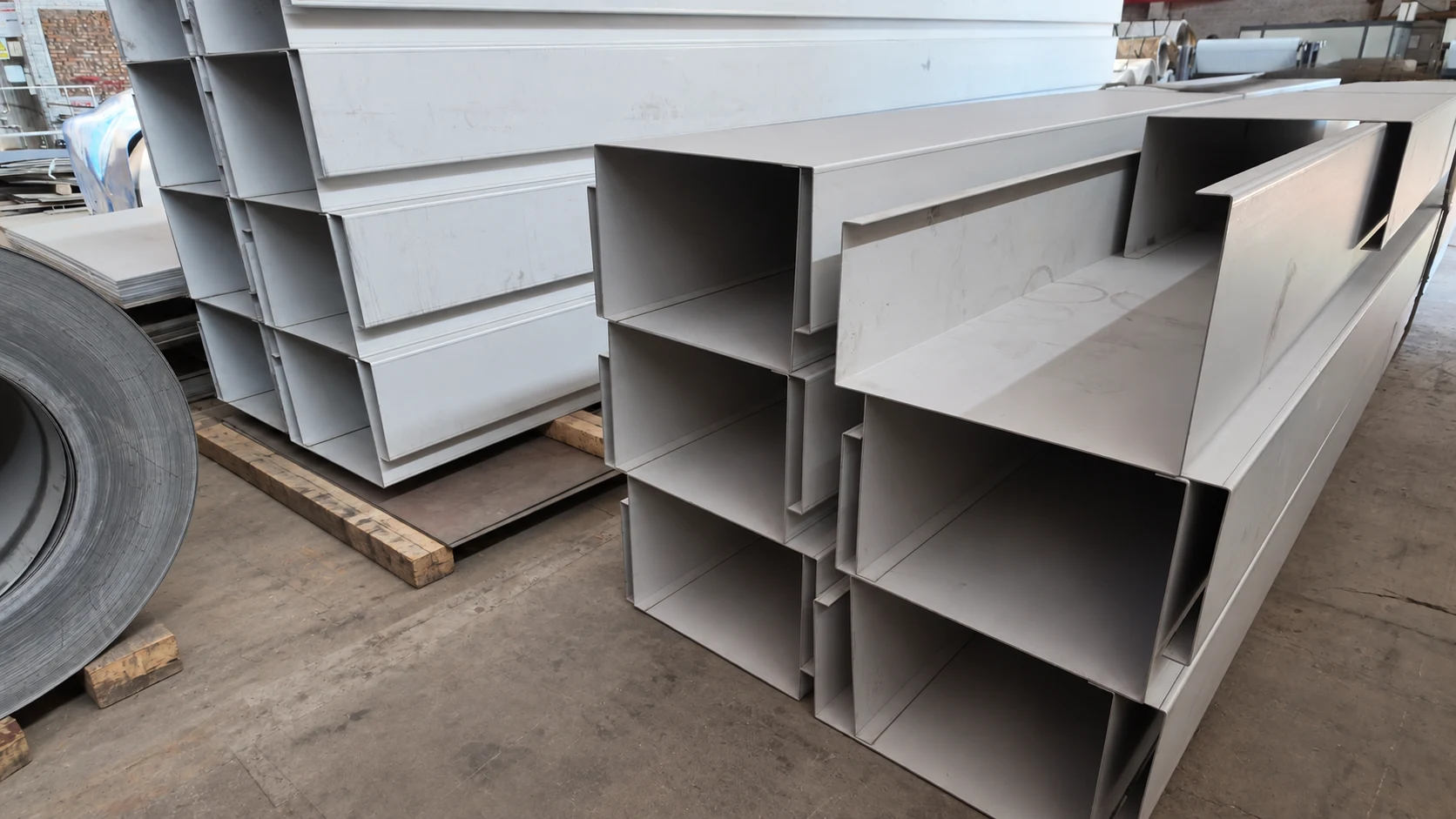
Where gutters are used
Roof gutters collect runoff and convey it to outlets and downpipes. Typical locations include industrial eaves, warehouse roofs, canopies and concealed roof valleys. A concealed gutter needs particular attention to overflow routes and access because a leak can affect the building below.
Stainless steel offers grade options for different exposures and can be formed into project-specific sections. Accessible open channels also permit inspection and cleaning. These advantages depend on correct detailing; stainless steel is not a substitute for maintenance or a guarantee against leakage.
Confirm the required waterway, fall, outlet positions, freeboard and overflow arrangement before reducing a section to suit stock width. The roof-drainage designer must establish rainfall demand and capacity. A wider bottom and a shallower side are not automatically hydraulically equivalent. See Euro Inox’s rainwater-goods guide for general application background.
Choose a grade for the exposure
| Exposure or purchasing situation | Grade to evaluate | Selection boundary |
|---|---|---|
| Ordinary inland rainwater, limited salt or industrial contamination | 304 / 304L | Starting candidates, subject to local deposits and cleaning access. |
| Marine-influenced or polluted exposure with a more demanding chloride risk | 316 / 316L | Evaluate the actual salt loading; 316L is not universally sufficient near the sea. |
| Severe coastal or industrial marine exposure | 2205 or a higher-alloy alternative | Requires application-specific material and fabrication review. |
| 430 proposed as a cost substitution | 430 only after exposure review | Interior suitability does not establish suitability for an outdoor wet gutter. |
| 201 or an unspecified “200-series” offer | Verify the precise grade and composition | Do not substitute on the series name or price alone. |
| Chemical exhaust condensate, process liquid or aggressive cleaning runoff | No default grade | Provide chemistry, concentration and temperature for specialist selection. |
The atmospheric rows are screening guidance adapted from Outokumpu’s exposure-based selection guidance; they are not an approval of a specific gutter. Grade numbers within a family are not interchangeable; worldstainless explains stainless steel families and grade differences.
Where welding is involved, consider the low-carbon L grades to reduce sensitisation risk. The L suffix does not remove the need for weld protection and cleaning. TWI explains low-carbon grades and sensitisation. Request the ordered grade, thickness, finish and material documentation together; do not identify grade from a photograph or a magnet test alone. Use our material test report verification checklist to prepare the document checks for the order.
Give each folded edge a job
| Section detail | Useful purpose | What must be checked |
|---|---|---|
| Plain U section | Simple open waterway with fewer bends. | Exposed edges, side-wall stiffness and support attachment. |
| Outward top flange | Provides a possible fixing or flashing interface. | Roof overlap, screw access, sealing detail, tooling clearance and increased envelope width. |
| Inward top flange | Can suit a cover or internal fixing detail. | Reduced clear opening, access for cleaning, tool collision and nesting interference. |
| Hem or additional return | Can shield a cut edge and stiffen the local lip. | Extra stock consumption and forming operations; avoid a poorly drainable dirt-trapping detail. |
| Different side heights or a back upstand | Can match a roof junction. | Handedness, flashing interface and designed overflow route. |
A lip that stiffens an edge does not establish the gutter’s load capacity. Specify supports, water loading and any snow or maintenance loads separately. An open 90-degree flange and a flattened 180-degree hem need different forming models.
For a four-bend flanged channel, review forming the short lips before the main walls, then simulate the whole sequence and removal from the tooling. This is a sequence to evaluate, not a rule for every section. Minimum flange length depends on the die opening; a narrow flange can fail to bridge the die, while a tall wall can hit the punch. Bystronic explains flange limits and tool interference. Confirm tooling, achievable radius, springback compensation, surface protection and support of the long workpiece.
A 1500 mm sheet: where the width goes
First define the dimension convention. Finished inside width, outside width, virtual-sharp dimensions and straight lengths between bend tangencies are different. Do not add dimensions taken from different conventions.
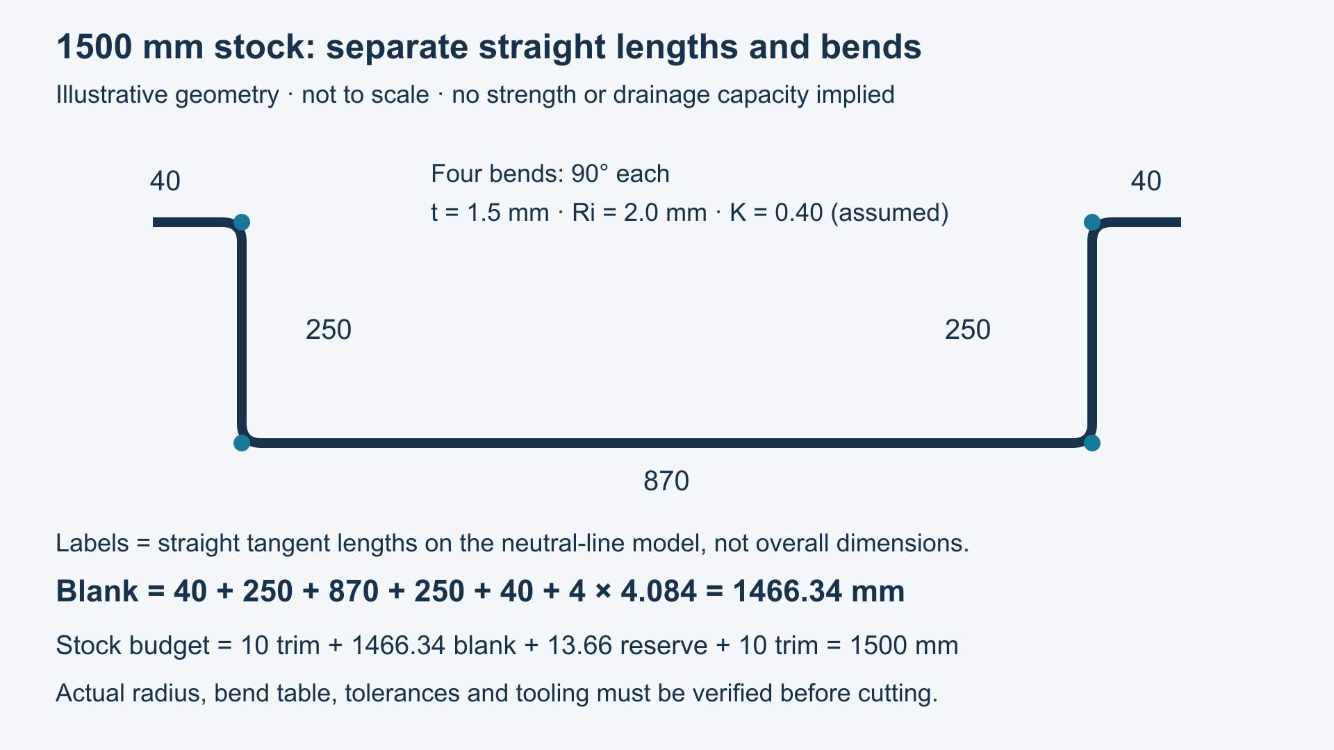
For the transparent example below, each labelled edge is a straight tangent length along the neutral-line model. The curved bend zones are counted separately. Assume a 1500 mm sheet, 10 mm reserved at each stock edge for trimming, thickness t = 1.5 mm, inside radius Ri = 2.0 mm and K = 0.40. These are calculation inputs, not recommended material, radius, trim allowance or a verified machine setting.
For each 90-degree bend, the assumed bend allowance is:
BA = (π / 2) × (Ri + K × t) = 4.084 mm
For four bends, the total allowance is 16.336 mm. The usable stock width after the assumed edge reservation is 1480 mm, leaving at most 1463.664 mm for the five straight tangent segments.
| Allocation, mm | Left lip | Left wall | Bottom | Right wall | Right lip | Blank with 4 bends | Remaining within 1480 |
|---|---|---|---|---|---|---|---|
| A: balanced example | 40 | 250 | 870 | 250 | 40 | 1466.34 | 13.66 |
| B: wider bottom | 40 | 250 | 880 | 250 | 40 | 1476.34 | 3.66 |
| C: taller walls | 40 | 300 | 770 | 300 | 40 | 1466.34 | 13.66 |
All dimensions in mm · Straight tangent lengths · Swipe to compare on mobile
All five edge columns are straight tangent lengths, not finished overall edge dimensions. Rows A–C illustrate stock allocation only. They are not equivalent drainage or strength designs. Row B’s small remainder is a prompt to check the real tolerance and trimming budget, not a recommendation to use the full width.
If the five straight lengths themselves total 1500 mm, four bend zones increase the estimated blank to 1516.34 mm before any trimming. Conversely, a calculation based on finished outside virtual-sharp dimensions normally uses a bend-deduction method. Do not add the above allowances to those outside dimensions as well: that mixes two conventions.
Autodesk documents unfold methods and material-specific bend tables. Use a measured bend table or validated trial for the actual material and tooling. Recalculate if the thickness, radius, angle or flange arrangement changes; the four identical allowances above do not apply to hems or unequal bends. Do not move fold lines by dividing the blank into five arbitrary bands.
Measure what needs to fit
The purchaser’s drawing should define finished clear bottom width, opening width, both side heights, flange direction and width, bend angle/radius, section length and the measurement datums. Identify the dimensions that control roof fit, outlet fit or connection to the next section. Leave the fabricator to derive a separate flat pattern using one consistent convention. Our stainless steel gutter specification guide provides a related reference when preparing the enquiry.
- Before cutting: check the actual sheet width and thickness; include agreed edge quality, trimming, squareness and the cutting method’s allowance in the layout.
- On the first formed section: measure left/right height, opening, bottom, lip widths and angles. Check both ends and intermediate stations to reveal bow, twist or variation along the length.
- After welding: repeat the interface measurements, inspect end plates and outlets, and check adjoining sections for fit. Record results against the agreed drawing revision.
- Before packing: check whether lips have been squeezed, ends opened or surfaces damaged during handling; record the accepted condition.
Agree numerical tolerances on the actual drawing. One blanket “±1 mm” promise would ignore length, section stiffness, welding and measurement conditions. Thickness and support spacing likewise need a project-specific check; a stock-width example cannot establish either.
Long runs also require a thermal-movement detail. Fewer fabrication joints do not eliminate expansion: the Euro Inox guide explicitly discusses thermal forces in connections. Fixed points, sliding supports and movement joints must be coordinated with the roof system.
Weld, clean and check
Define the joint
At end plates, outlets and site joints, define the joint preparation, fit-up, weld access and acceptance criteria before production. For a joint intended to be watertight, intermittent welds alone leave unwelded paths; any alternative sealed-joint system needs its own approved detail.
Prepare and protect
Remove film, adhesive and contamination from the weld area using a compatible procedure. Keep stainless work away from carbon-steel grinding debris and use clean dedicated tools. Select filler, shielding and heat-input controls through the applicable welding procedure; duplex steel needs its own procedure rather than a copied 304 setting. See the IMOA duplex fabrication guide, section 12.
Control distortion
Plan tack positions, joint restraint and a balanced welding sequence. Excessive heat and shrinkage can distort long thin sections; remeasure after cooling. TWI explains austenitic stainless weld distortion. A back-step or distributed sequence, if used, must still produce the required continuous finished seam.
Remove heat tint
Protect the exposed weld root as required by the procedure. Heat tint is not just a colour issue: it can accompany chromium depletion and lower corrosion resistance. Root shielding reduces its formation; post-weld cleaning must address both oxide and the affected surface layer. TWI’s heat-tint guidance. Confirm that the cleaning procedure removes the oxide and affected layer; a bright appearance alone is not an acceptance criterion.
Agree the leak check
Agree a leak-check method, test extent, acceptance criteria, documentation and repair/retest steps. A visual inspection or a local factory test does not prove installed drainage capacity or every site joint. Any water test needs a controlled support and loading arrangement, clean suitable water, and drying afterward.
Pack around the section geometry
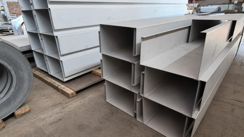
“Vertical stacking” is ambiguous. Sections can be layered upward while their long axes remain horizontal, carried on edge in a restrained rack, or stood on their ends. These are different arrangements. Long gutters should not be treated as suitable for end-standing merely because a side wall looks straight.
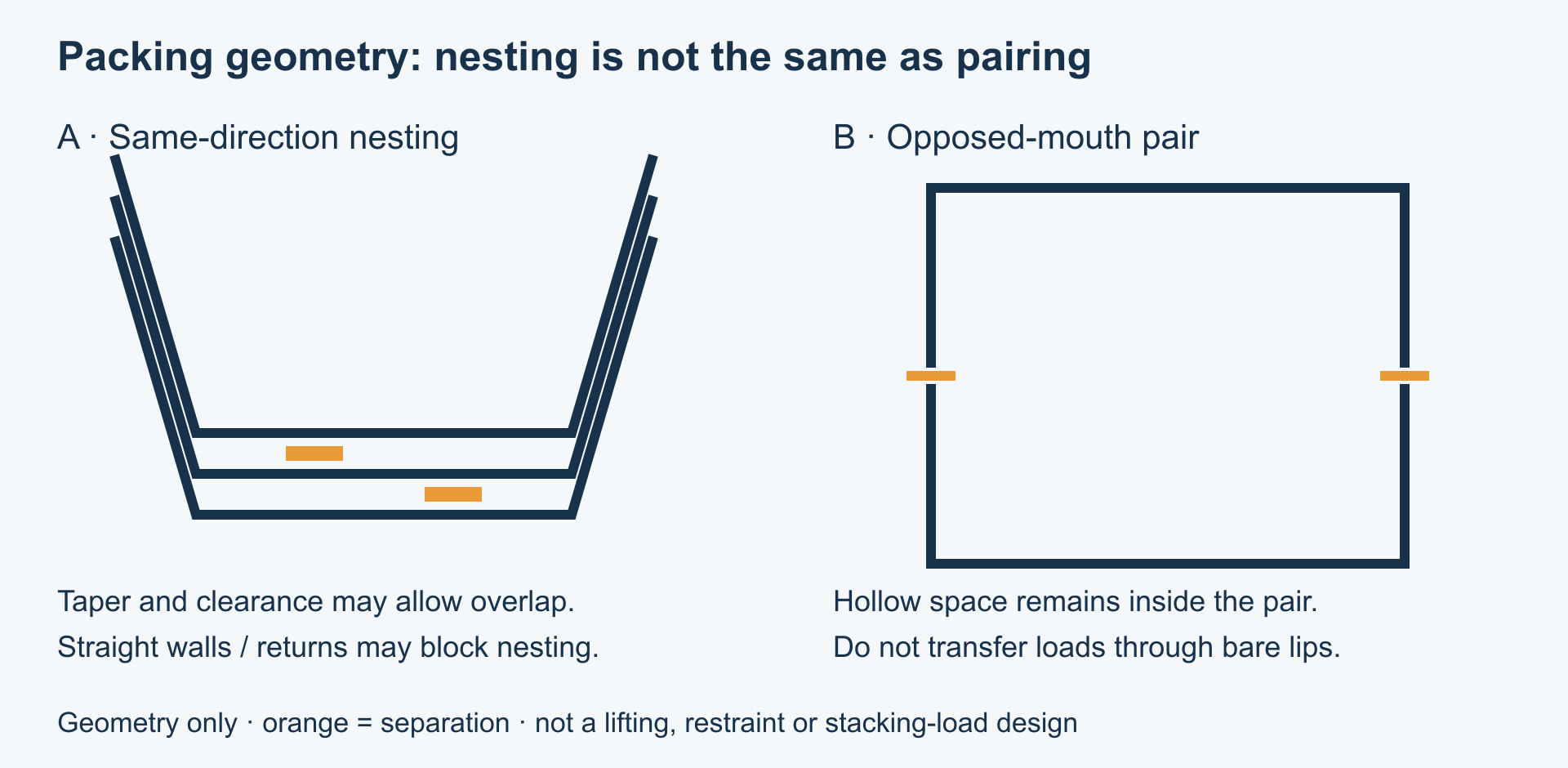
Same-direction nesting
Open profiles with adequate taper and clearance, without obstructing returns, outlets or end plates.
May reduce pack height, but tight nesting can jam, scratch or distort the sections.
Horizontal sections layered upward
Profiles supported by a cradle/separator system that carries load without relying on thin lips.
Works even where deep nesting is unavailable, but accumulated load and stability must be checked.
Opposed-mouth pairing
Profiles that can be paired without flange or attachment interference, with designed separation and support.
Retains a hollow envelope; usually uses more volume than deep nesting of nestable sections.
On-edge storage in a rack
A purpose-designed, padded, laterally restrained rack.
Needs an assessed load path and stability; unrestrained leaning risks tipping and distortion.
Identical straight-wall U sections do not necessarily nest. Wall thickness, fold radii and returns can block entry. Do not force one section into another or change the specified section merely to improve packing.
Opposed-mouth pairing may shelter the open lips, but it does not automatically halve freight volume or carry stacking loads safely. Compare the external pack dimensions, number of sections per pack, gross weight and protection cost for the actual alternatives. If nesting is impossible, a separated pair may be a reasonable compromise.
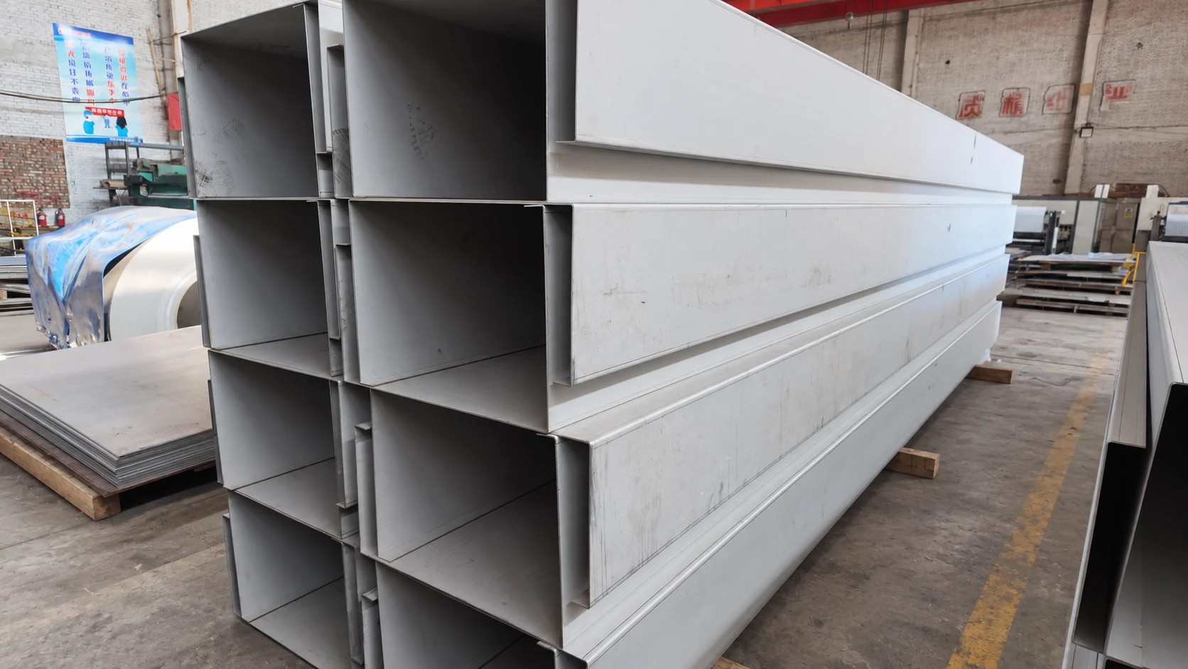
For a transport plan, ask for clean non-abrasive separators, supports located to control long-section sag, and restraints acting through suitable protective spreaders rather than bare flange edges. Isolate carbon-steel contact, protect against grit and strap abrasion, and prevent water from remaining in absorbent packing. These surface-protection principles are consistent with the storage and packaging section of Outokumpu’s corrosion-resistance guide; the precise gutter stack and restraint design must be checked separately.
Film is not a structural separator. Keep it only within its supplier’s permitted storage, weather and removal conditions, and remove it locally before hot work. On unloading, lift separated sections rather than dragging them lengthwise. Check for rubbing, dents, compressed lips and embedded debris. A scratch does not by itself prove permanent loss of corrosion resistance, but surface acceptance and contamination still need attention.
What to send with your enquiry
For a ZEMSS enquiry, send the installation country and exposure, proposed grade and thickness, finished section drawing with datums, length/quantity, outlet and end-plate details, finish and protected faces, tolerance and inspection requirements, and delivery destination. Include access or unloading restrictions and whether transport volume is a priority.
Ask the quotation to identify the agreed flat-pattern basis, fabrication and inspection scope, and proposed packing envelope. This allows material, forming and delivery assumptions to be compared before ordering. Review the cutting, forming and welding services relevant to your drawing, then send the drawing and project inputs through the ZEMSS fabrication enquiry form.