

A large tank is only one part of a fabrication package. Its nozzles must meet the pipework, its access components must fit the installation, and the accompanying chambers and mixers must follow their own drawings. This stainless steel tank fabrication case study follows one project through those connected decisions, using original drawing excerpts and workshop photographs.
The package covered a urea solution storage tank, two process chambers, ammonia injection grids and static mixers for an industrial flue-gas treatment project. The photographs show fabricated assemblies in the workshop. The discussion follows the manufacturing workflow and explains the checks associated with each stage; it does not present site commissioning results or a photographic record of every operation.
Planning a similar package? Start with our custom stainless steel tank fabrication service, or send your drawings for a fabrication review.
What the project included
The supply scope contained five equipment groups, totaling nine sets. They shared a project, but they did not share one material specification or one inspection checklist.
| Equipment group | Quantity | Fabrication focus |
|---|---|---|
| Urea solution storage tank, ladder and manway | 1 set | Shell geometry, bottom reinforcement, nozzles and access interfaces |
| Process chambers | 2 sets | Long cylindrical bodies, conical transitions and connection alignment |
| Ammonia injection grids | 2 sets | Pipe branches, openings, orientation and supports |
| Static mixer types 1–2 | 2 sets | Vane profiles, arrangement and attachment details |
| Static mixer type 3 | 2 sets | Annular geometry, internal vanes and assembly interfaces |
For a buyer, this is a useful way to divide a request for quotation. A single description such as “stainless steel equipment” leaves too much unresolved. The tank, internal flow components and access steelwork need separate drawing references, quantities, material lines and acceptance requirements.
1. Read the assembly drawing before preparing individual parts
The tank drawing specifies a 2,000 mm diameter and a 3,000 mm straight shell height. Those figures establish the main cylindrical geometry; they do not establish usable storage capacity. Working level, internal details and the complete vessel configuration still need to be considered by the designer.
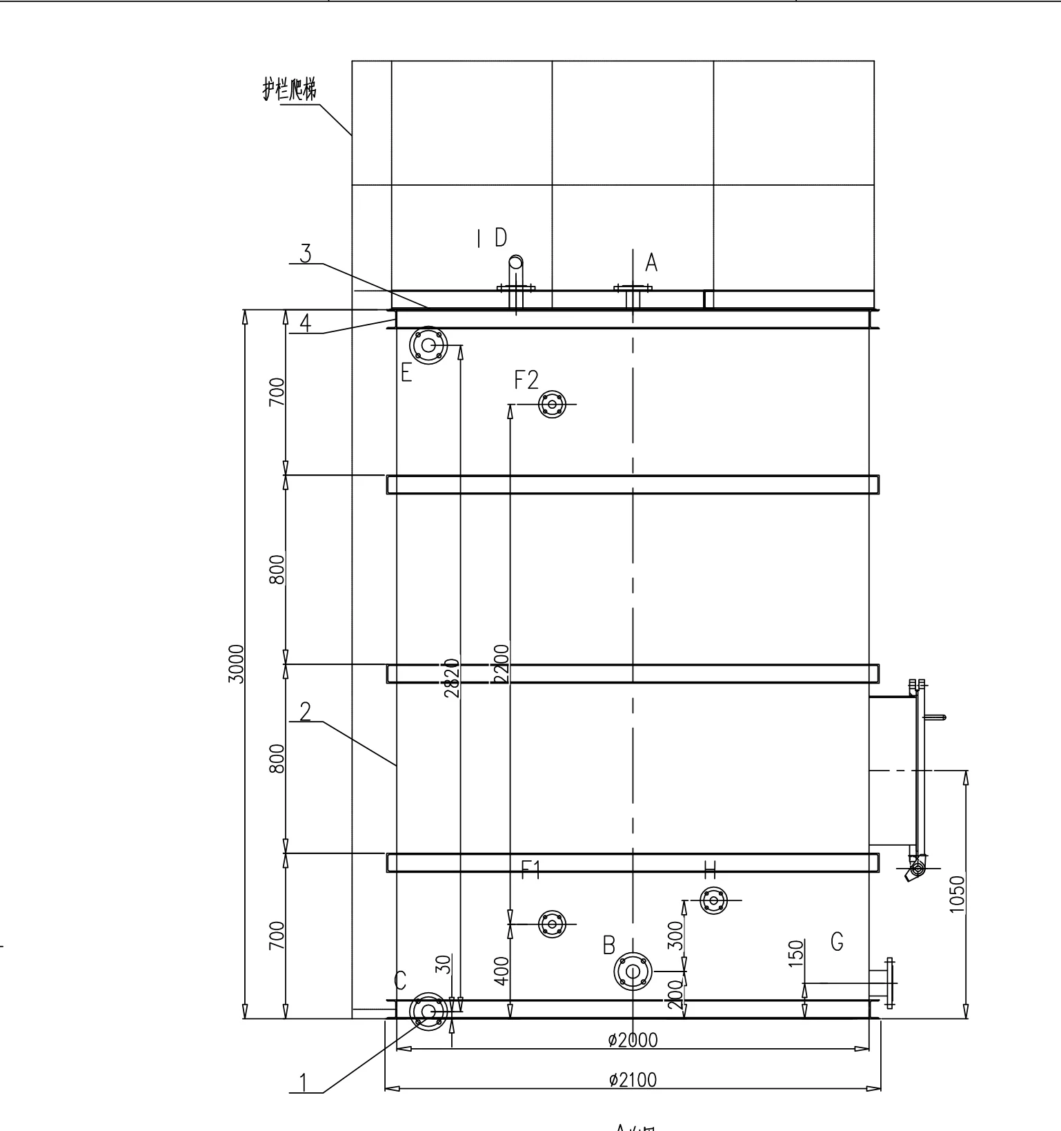
The elevation shows the shell, external rings and nozzle positions. Other views and schedules supply information that a front elevation cannot: connection orientation, flange details, reinforcement, access and individual component dimensions. Reading these together helps prevent a correctly made part from being attached in the wrong place.
Before releasing parts for fabrication, a drawing review should resolve:
- Revision control: which assembly drawing, detail sheets and material schedule govern the order.
- Datums: where heights, angles and connection positions are measured from.
- Interfaces: which dimensions must meet site pipework, foundations or another fabricated assembly.
- Inspection access: which joints or dimensions will become difficult to examine after assembly.
- Supply boundaries: whether instruments, fasteners, gaskets, insulation, coatings and site installation are included.
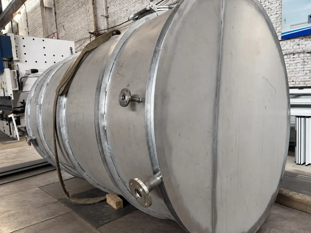
The horizontal position of the tank in the workshop photographs must also be distinguished from its installation arrangement. A photograph is useful evidence of construction, but the approved drawing remains the reference for how the equipment is intended to be installed.
2. Assign materials by component, not by the project name
The tank drawing lists 304 stainless steel plate at 4 mm for the main tank construction. The process chamber drawing lists 304 stainless steel at 5 mm for its main cylindrical body. Separate mixer and injection-grid drawings introduce other material requirements, including 310S stainless steel and carbon steel components.
These are drawing specifications. A finished surface cannot prove an alloy grade, and a material certificate is relevant only when it can be traced to the material actually used in the identified component.
| Component | Drawing information | Buyer’s check |
|---|---|---|
| Main storage tank construction | 304 stainless steel, 4 mm plate | Match plate identification and thickness to the tank material schedule. |
| Main process chamber body | 304 stainless steel, 5 mm plate | Keep its plate requirements separate from the storage tank’s. |
| Static mixer types 1–2 | 310S stainless steel specified on the component drawing | Identify the applicable mixer type before selecting material. |
| Injection-grid pipework and supports | 304 pipework with separately specified carbon steel supports | Separate wetted or process-contact parts from support steelwork. |
Carbon steel reinforcement or access parts do not make the whole tank a carbon steel tank. Equally, a stainless steel shell does not mean every bracket, fastener or associated mixer has the same alloy. A component-level bill of materials makes those distinctions visible before purchasing and fabrication begin.
3. Develop, cut and form the shell and reinforcement
A cylindrical shell begins as flat material, so the fabrication plan must convert the drawing into plate developments and a forming sequence. The practical questions include joint locations, forming allowances, edge preparation and access for subsequent welding. Plate thickness, diameter and the approved joint arrangement govern these decisions; a generic cutting layout is not enough.
During forming and fit-up, the shell needs checks for diameter, roundness and edge alignment against the drawing’s tolerances. External rings and bottom stiffeners add another set of interfaces. Their location affects later attachment work and should be coordinated with nozzles and access components.
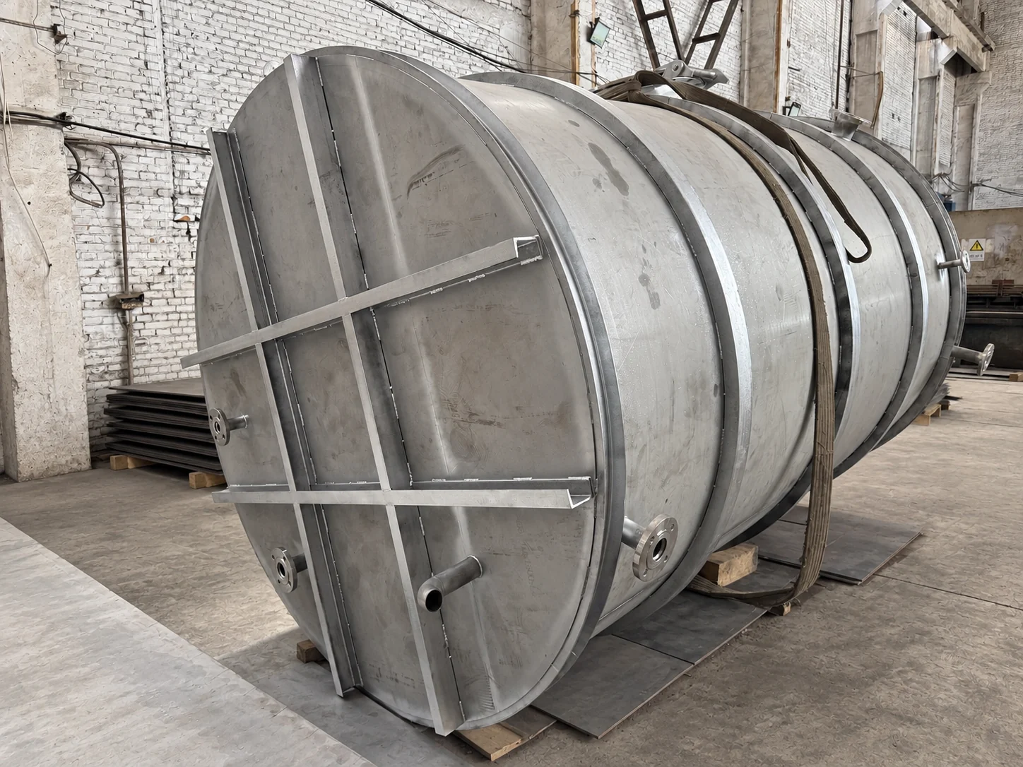
The photograph above shows the bottom end with crossed stiffeners and reinforcement around the shell. It makes the construction understandable in a way that a capacity figure cannot. It does not, by itself, establish plate thickness, dimensional tolerance or load capacity.
For a similar order, ask how the fabricator will record the dimensions that matter to your installation. An overall diameter check is useful, but it cannot replace measurements of nozzle position, attachment spacing or mating faces.
4. Control fit-up and welding around the final geometry
Shell seams, bottom joints, reinforcing rings and nozzle attachments create different welding conditions. Welding sequence and restraint need to be considered together with access and dimensional checks. The objective is to maintain the geometry required by the drawing while producing joints that meet the agreed acceptance criteria.
TWI’s guidance on distortion control during fabrication explains the roles of assembly technique, tack welding and restraint in controlling movement. That is general fabrication guidance; it is not a record of a particular welding procedure used on this project.
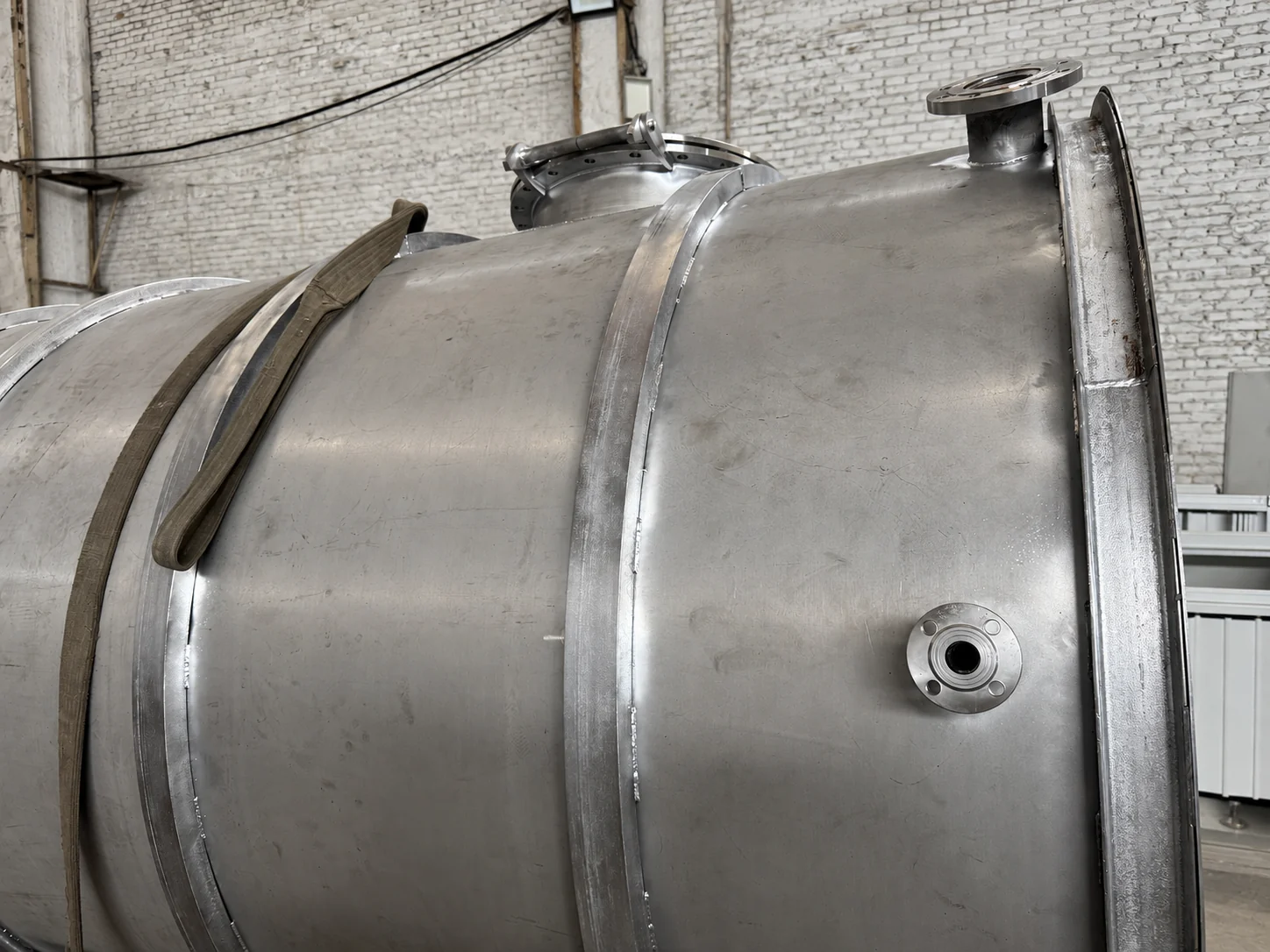
This close view shows how a shell, ring and nozzle occupy the same working area. An attachment that appears simple on a drawing can restrict welding or inspection access once adjacent parts are fitted. Planning the order of work matters particularly where several features meet.
For procurement, define the welding documentation and inspection scope before production. Where the project requires qualified procedures, welder qualifications, a weld map or non-destructive examination, those requirements should identify the applicable joints and acceptance criteria. A photograph of a weld surface is not a substitute for that documentation.
5. Check nozzle purpose, size and orientation separately
The tank nozzle schedule distinguishes filling, outlet, drain, vent, overflow and instrument connections. For example, the drawing lists a DN40 filling connection, DN25 outlet and DN50 drain. These sizes describe different services and should not be treated as interchangeable openings.
A useful nozzle review checks four things together: the connection’s function, nominal size, location and interface details. A nozzle can have the correct diameter yet still cause installation problems if its orientation, projection or flange arrangement is wrong.
- Identify each connection using the drawing’s nozzle mark.
- Measure its position from the specified datum.
- Check the connection face and bolt-hole orientation where applicable.
- Check accessibility for instruments, valves and maintenance.
- Confirm which mating parts are supplied by the fabricator and which are supplied at site.
A flange designation must also be read in context. A nominal pressure marking on a flange does not, on its own, establish the design pressure of the complete tank. Pressure, temperature and service conditions belong in the equipment specification and design documentation.
6. Treat the long process chambers as a separate fabrication task
The same project included two long cylindrical process chambers with conical end transitions. Their fabrication challenges differ from those of the larger storage tank: the long axis, transition geometry and connection alignment become prominent features of the assembly.
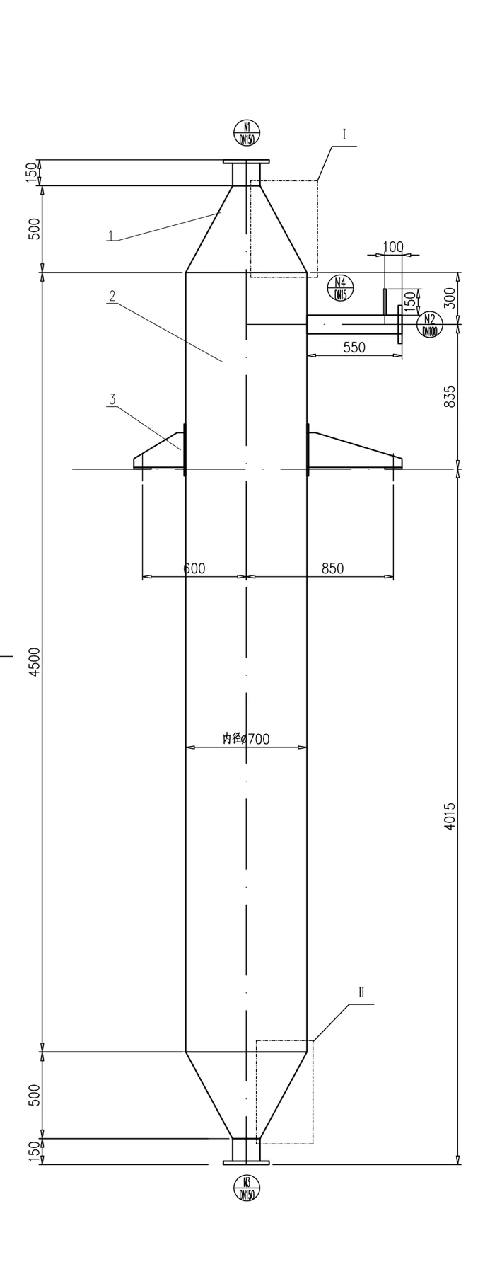
The drawing excerpt shows the chamber’s cylindrical body and end transitions. Read it with the complete connection and support details when preparing fabrication or inspection instructions. A cropped drawing helps explain the geometry here; production must use the complete approved drawing set.
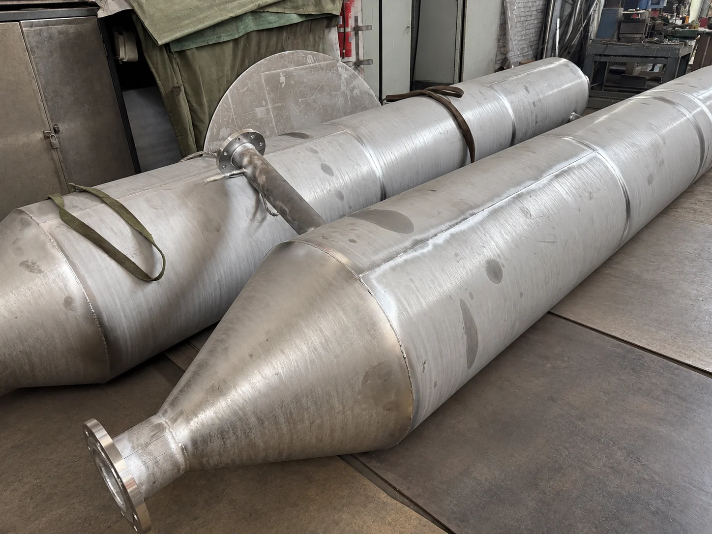
The workshop photograph shows the pair of chambers and their conical ends. It provides a visible comparison with the drawing’s overall arrangement. It cannot establish internal dimensions, operating temperature, pressure performance or the behavior of the installed process.
For comparable equipment, the fabrication review should cover alignment along the body, fit-up at cylindrical-to-conical joints, connection positions and handling arrangements. Any internal features that become inaccessible after closure should have their inspection point identified earlier in the manufacturing plan.
7. Translate injection-grid drawings into identifiable pipe assemblies
The ammonia injection grid is another distinct fabrication item. Its drawing combines an overall pipe arrangement with branch and section details. Those views need to be reconciled before cutting pipe, making openings or attaching supports.
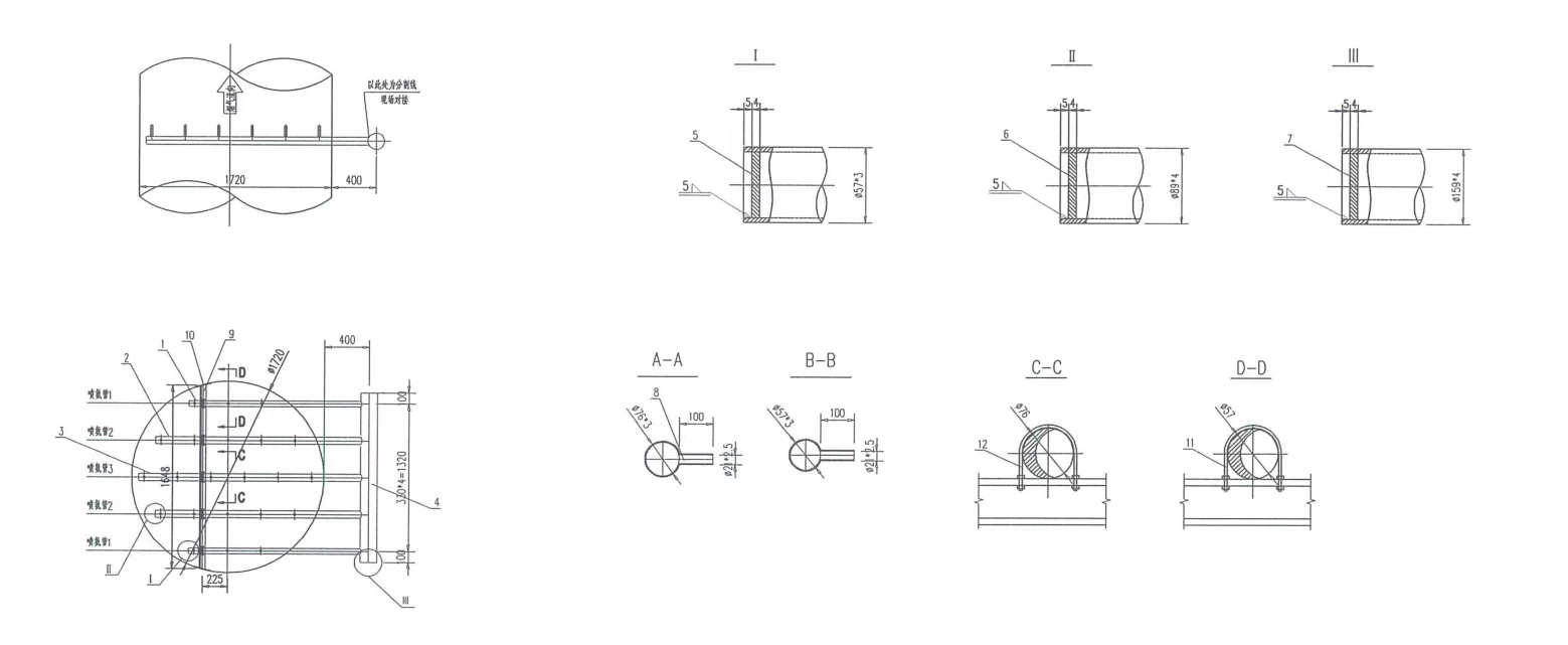
For ammonia injection grid fabrication, branch positions and opening directions are part of the design. An assembly should not be accepted only because its outside dimensions fit the available space. Pipe lengths, branch spacing, opening details and installation orientation need to be checked against the approved drawing.
The fabrication scope must also distinguish making the specified geometry from validating the process design. A drawing-based manufacturing case does not demonstrate ammonia distribution uniformity or emissions performance. Those outcomes require the appropriate design analysis and operating evidence.
8. Read static mixer vanes as three-dimensional parts
The package contained more than one static mixer type. Their drawings should remain separate throughout material purchasing, cutting and assembly. A similar-looking annular shape does not establish that two mixers have the same material or vane geometry.
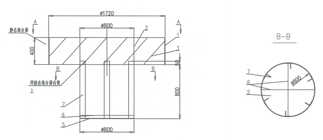
The drawing excerpt includes an assembled section and a circular section view. Vane profiles, placement and attachment details must be interpreted with the complete drawing. Overall diameter alone is insufficient to define a static mixer.
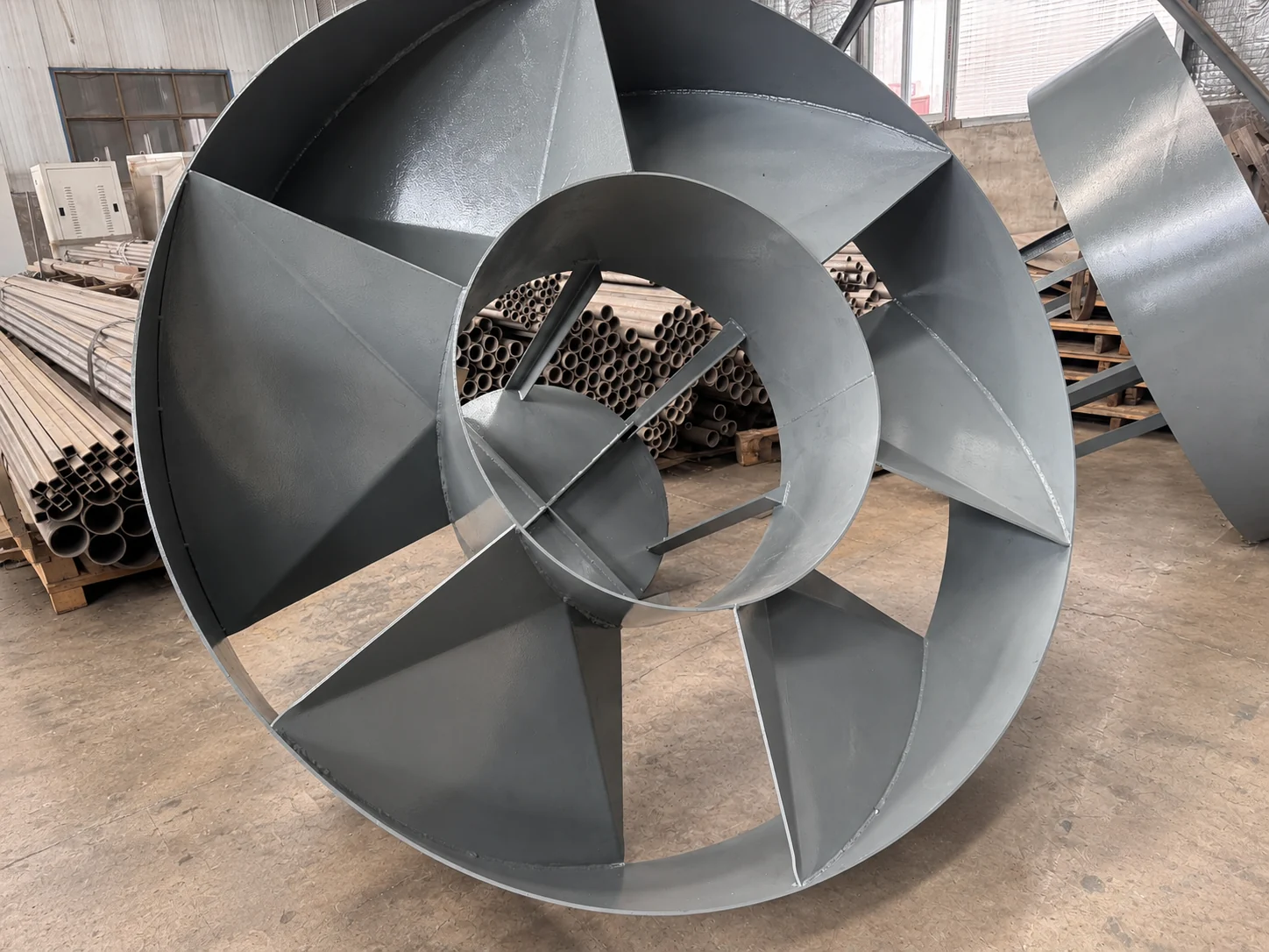
The project photograph shows an annular mixer with angled vanes. It helps readers understand what the assembled geometry looks like. Without a traceable component identifier and dimensional record, the photo should not be used as proof of compliance with every dimension on a particular mixer sheet.
When ordering a static mixer from drawings, specify the drawing revision, material, vane arrangement, attachment details and the dimensions needed to fit the receiving duct or chamber. Performance requirements should be stated separately from manufacturing acceptance requirements.
9. Include access steelwork, finish and handling in the scope
Access components are easy to leave until late in a quotation, yet their attachment points have to agree with the main equipment. The project included tank access items, and the workshop photographs also show an access guard cage.
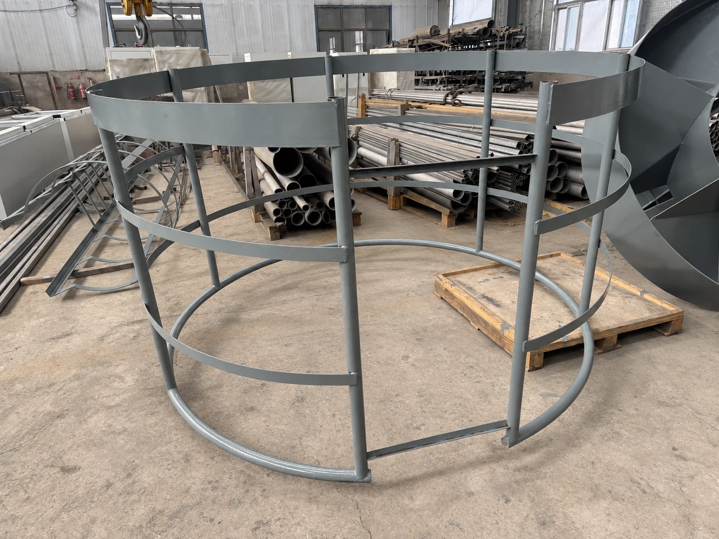
Check attachment spacing, installation clearance and the boundaries between shop assembly and site assembly. Do not assume that every separately photographed accessory is already installed on the tank. Packing and identification should make those relationships clear to the receiving team.
Surface requirements need similar precision. The appearance of a workshop photo does not establish a specified roughness, coating thickness or chemical surface treatment. State the required finish and how it will be assessed in the order documents.
For stainless steel work, avoiding contamination from carbon steel tools and handling equipment is a relevant fabrication consideration. worldstainless guidance on cleaning stainless steel discusses contamination and suitable cleaning practices. The treatment required for a particular assembly must still follow its service conditions and agreed specification.
10. Separate inspection requirements from inspection results
The chamber drawing calls for a 48-hour water-fill test. That is an instruction defining a required check; it is not evidence that an identified chamber completed the test successfully. This case study does not present a signed test report or claim a verified test result.
This distinction is useful when reviewing any fabrication supplier’s documentation. A blank form shows what might be recorded. A completed record must identify the equipment, describe the actual test conditions, record the observations and carry the required authorization.
| Evidence | What it supports | What to verify |
|---|---|---|
| Approved fabrication drawing | Required geometry, materials and specified checks | Revision, approval status and consistency across detail sheets |
| Material certificate and traceability record | Identity and reported properties of a material batch | Connection between that batch and the actual component |
| Dimensional inspection record | Recorded measurements on identified equipment | Datums, drawing tolerances, measured values and acceptance |
| Completed leak-test or examination report | Results under the documented test conditions | Equipment identity, method, conditions, observations and sign-off |
| Workshop photograph | Visible construction and condition at the time photographed | Component identity and the limits of what the image shows |
A water-fill leak test should not be described as proof of a pressure rating without the relevant design and test basis. Likewise, external appearance cannot establish weld soundness throughout a joint. The inspection method needs to answer the acceptance question being asked.
11. Prepare an equipment-specific handover package
A useful handover package connects the physical assemblies to the drawings and records. For an order of this kind, agree the required deliverables before fabrication rather than attempting to reconstruct them from photographs at the end.
- The applicable drawing list and final revisions, with approved changes identified.
- An equipment and loose-parts list that distinguishes tanks, chambers, grids, mixers and accessories.
- Material traceability documents required by the purchase specification.
- Dimensional, welding and test records required by the agreed inspection plan.
- Finish, cleaning and preservation information where specified.
- Packing identification and handling information appropriate to each assembly.
The photographs in this article stop at the workshop stage. They are useful for understanding the fabricated package, but delivery acceptance, site assembly and commissioning are separate milestones with their own records.
What to send for a comparable fabrication quotation
For custom stainless steel tank fabrication or a mixed equipment package, send the complete drawing set and a short description of the intended service. Include operating conditions, material requirements, quantities, inspection expectations and delivery location. Identify any interface dimensions that your installation cannot accommodate changing.
If the drawings are still being developed, list the open decisions explicitly: capacity and working level, nozzle schedule, support arrangement, mixer geometry, surface finish or required documentation. That allows the fabrication review to distinguish a missing design input from a shop manufacturing detail.
Cost and lead time depend on more than metal weight. Part variety, forming work, weld access, dimensional requirements, inspection scope and the extent of documentation all affect the work. Comparing quotations against the same drawing revision and acceptance scope gives a more useful result than comparing an undifferentiated price per kilogram.
Email your drawings for a fabrication review and include the equipment list, material requirements and inspection deliverables. The email opens with this case study as its reference. You can also upload drawings through our enquiry form. For tank-specific enquiries, see our stainless steel tank fabrication page.
Case materials: original project fabrication drawings, the project equipment scope and workshop photographs. Drawing excerpts are presented for explanation; they are not a complete manufacturing drawing set. General technical references are linked beside the points they support.